Measuring Motor Revs. Per Inch
Overview
This document describes the steps required to correctly calculate and measure the motor revs/inch ratio for your machine. It further explains how to check and/or correct these values in the parameter settings of a Centroid CNC Control.
Required Tools
A known accurate measure (for the example a 10" gauge block will be used). 1.
Calculator, pen or pencil. 2.
Setup steps
1. From the main screen in the CNC7 software, press the following keys in order to get into the following parameter
screen. F1 − Setup, F3 − Config, Enter the password 137 − Enter, F2 − Machine, and then F2 − Motor. Enter the current ratio values into the chart below for Motor Revs/Inch. 2.
| Current Ratio | New Ratio − after | |
| Motor Rev/In | Calc. or measure | |
| X | X | |
| Y | Y | |
| Z | Z | |
| W | W |
Method 1 − Calculated, assuming ballscrew pitch and pulley ratios are known:
Using the following formula, calculate and enter the correct motor revs/inch value in the machine parameter screen as shown above.
Formulas:
tpi = 1/pitch
ratio = # of teeth on ball screw pulley / # of teeth on motor pulley revs/inch = tpi * ratio
Key:
tpi = Turns per inch of the ball screw (given) pitch = Pitch of the ball screw (given) ratio = The gear ratio of the pulleys (calculated) revs/inch = Motor revs per inch (calculated)
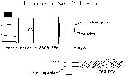
Example: See Diagram 2 on next page.
tpi = 5 Ratio = 48/24 = 2 Motor revs/inch = tpi*Ratio Motor revs/inch = 5*2 Motor revs/inch = 10
Note, this method assumes that the pitch and gear ratios are known. It is not uncommon that slight corrections based upon a measured test produce more accurate positioning throughout the entire axis travel. However, entering a Motor revs/in value based upon stated specifications should eliminate any gross errors.
Method 2 − Measured, assuming you have an accurate measuring method:
(NOTE: This method may also be used if the pulley ratio is unknown.)
Secure a 10" gauge block to the table. 1. Indicate one end of this block and set a part zero. Use probing cycles if you have this option. 2. Find (or probe) the opposite end of the block and record the distance the DRO displays. 3. Using the formula below, calculate the new motor revs/inch value: 4.
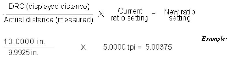
Finish
-
From the Machine Configuration, press
Motor and use the arrow keys to change the values Motor revs/inch . PressSave to accept the changes. Repeat the measurements again to verify that the new settings ar e correct. - To measure the backlash on each axis, see